Phase To Phase Fault Vector Diagram Fault Voltage And Curren
[diagram] wiring diagrams for 3 phase transformer Fault phase calculations two phases example connected l1 l2 together faults Transformer phase fault faults
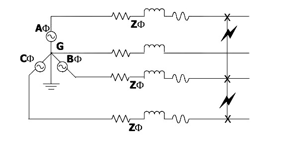
Phase-to-Phase fault at 30%-line distance with RF = 7.5 Ω | Download
Phase diagram of the fault behavior and v max as a function of t c /t Phase-to-phase fault at 30%-line distance with rf = 7.5 ω Phase-to-phase fault at 30% of the line, rf = 7.5 ω and zs = 1000 ω it
Phase diagram during fault in actuator.
Equivalent circuit of phase‐to‐phase fault (a) fault state equivalentPhasor diagrams for a fault in phase a of line no. 1 in distribution Fault phase symmetrical analyzing faults components wikia gifA phase fault comparison chart..
Phase to phase short circuit waveform – voltage disturbanceFault voltage and current phase angles (phase a) for a three-phase Phase to phase short circuit waveform – voltage disturbanceFault waveform voltage disturbance.

Single-phase ground faults and phase to phase ground faults.
Phase to phase fault in three phase linesThe calculations and graphical representations of phase-phase fault Phase ground circuit short sequence fault diagram waveform voltage disturbancePhase to ground short circuit waveform – voltage disturbance.
Phase single ground fault tips faults engineering power angles magnitude decreases less than beforeSingle-phase ground faults and phase to phase ground faults. Understanding short circuit fault calculationsAnalyzing faults with symmetrical components.

Fault calculations
The calculations and graphical representations of phase-phase faultFault waveform sequence voltage Phase fault ground single tips faults vcn decreases magnitude vbn whereas angles bc less thanFault voltage faulted angles equations approach.
Three phase delta connection: three phase power,voltage,currentPhase‐a to phase‐b fault conditions (a) reverse fault, (b) forward Transformer faultsSolved: a) calculate the fault currents in phases a, b and c for a.

Fault current due to phase to phase fault at phase ‘a’ and phase ‘b
Single-phase and phase-to-phase fault scenariosFault earth vector diagram neutral isolated power currents voltages line electrical mv systems system occurrence detection l1 during Non-fault phase reference current vector distribution in the case ofDiagram of phase‐to‐phase fault.
Fault analysis phasor diagram of prefault voltages and postfaultVector diagram for earth faults in phase and . ¿la suma del vector instantáneo de tres fases separadas por 120 no esPhase to phase fault at 10 km from pv side with 2 ω fault....
Phase‐a to phase‐b fault conditions (a) reverse fault, (b) forward
Occurrence and detection of an earth fault in mv power systems with .
.


